Would you like to build your own version of the automated, Arduino-based throttle I recently built for Chuck’s layout? Well, read on!
For those of you not already familiar with this project, Chuck wanted a throttle to automatically send two trains around a loop, in sequence, in opposite directions. Sounds like another job for Arduino!
Components
Arduino Pro
An Arduino Uno, the most common and popular version of the Arduino microprocessor board, would work fine. I used a stripped-down version, the Arduino Pro, which is made for permanent installations.
SparkFun Ardumoto Shield
The simplest way to control motor speed and direction is to use a motor-control chip. For reasons discussed earlier, I went with an L298 chip. The Ardumoto shield is a ready-to-use L298 with the necessary supporting components.
IR sensors
Chuck had IR sensors from Berkshire Junction already installed on the layout, and to be honest, I know very little about them. I attached the Chuck’s cables to the circuit as directed, and it worked. Any IR-LED-and-phototransistor pair should do the job, but they may need different resistors from what I have in the schematic below.
Indicator LEDs
I used some 5mm LEDs I had lying around, they’re old and kind of dim. Whatever you use, just make sure you pair it up with the appropriate series resistor. (How do you calculate the proper resistor value? It’s easy!)
Potentiometers
A 10K linear pot is all you need to feed an analog value from a knob. I used Panasonic’s readily-obtainable EVU-F2AF30B14.
Power Supply
Chuck wasn’t satisfied with the top speed we were getting with a 12V power supply. Because there will be a little voltage drop through the L298 chip, 12V in won’t yield 12V out. He scored a 15VDC, 1.6A wall wart, which gave his desired performance. Unless you run your own trains at full throttle (I don’t), a 12V supply should work fine.
Track
Chuck had all the trackwork done before I got involved. The staging setup, concealed from spectator view, looks like this:

Note that the diodes permit operation in one direction only on each of the staging tracks.
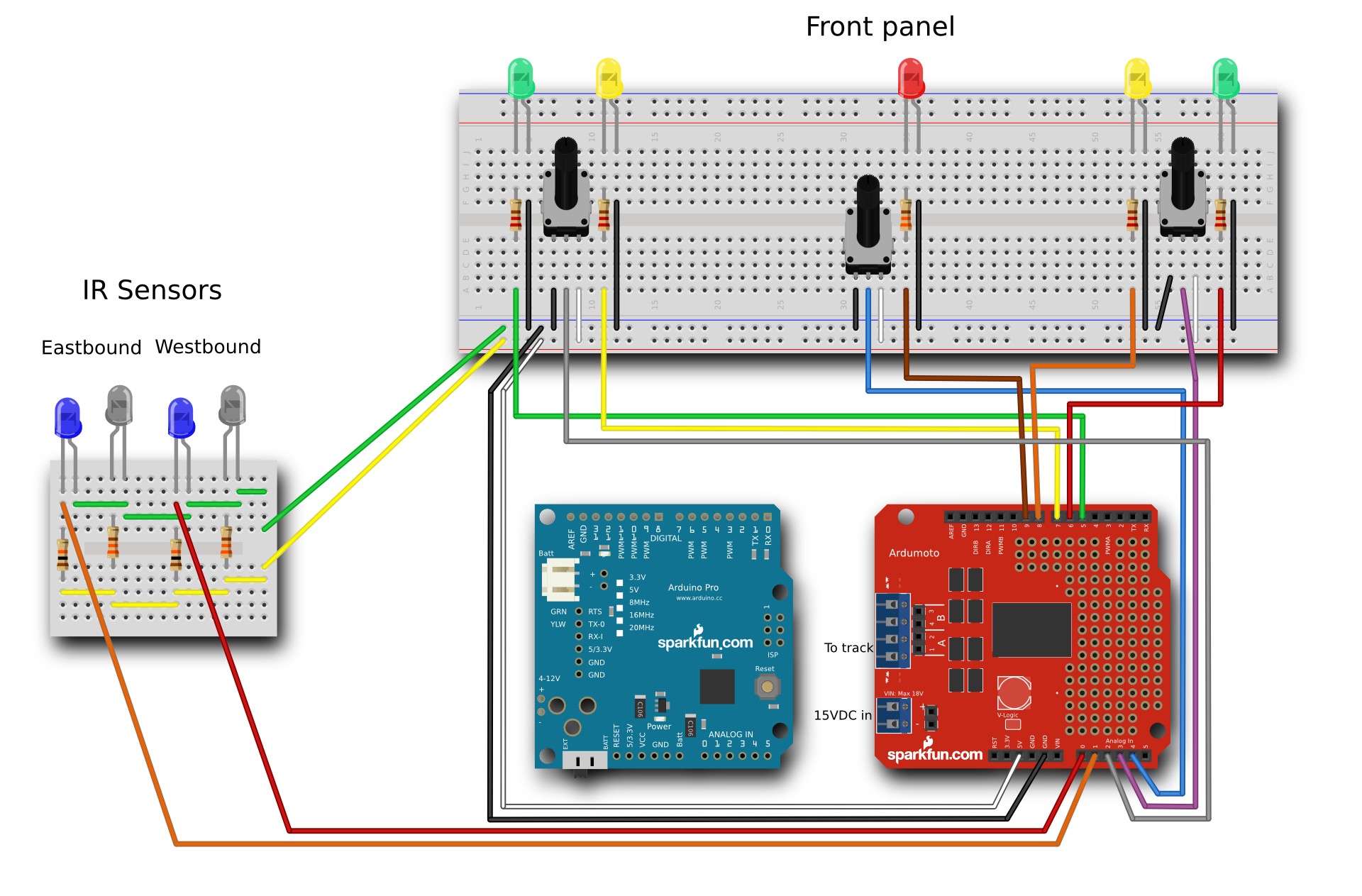
Circuit
Here’s a diagram of the breadboarded circuit:
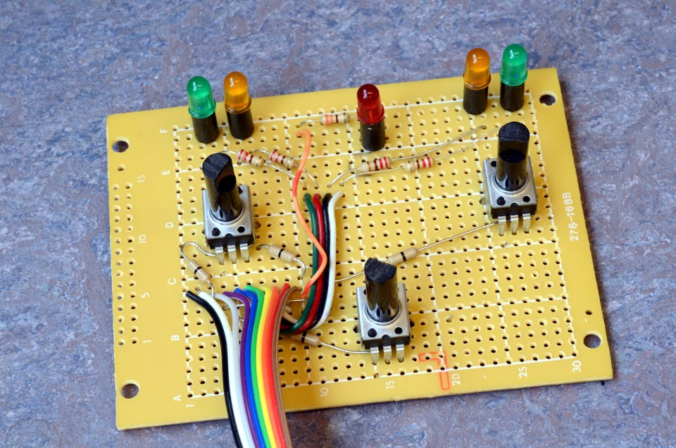
My permanent version looks like this:

The connections to the front panel and the layout sensors are made using the Protoshield at the top of the stack. SparkFun sells short lengths of ribbon cable and connectors, which help keep things tidy.
Code
Here’s the Arduino code that went into Chuck’s throttle, with some additional comments. Those of you with some Arduino experience might notice an unfamiliar declaration, enum:
enum mode {
  STOP, START, RUN, SLOW};
enum directions {
  EASTBOUND, WESTBOUND};
Enum is handy for defining things like running modes or directions of travel, as I’ve done here. You can then declare your variables to be an enumerated type:
mode runMode = START;
or just declare them as integers, and change values mathematically when desired:
int directionOfTravel = EASTBOUND;
...
directionOfTravel = 1 - directionOfTravel;
Very useful stuff!
If you have a question about the throttle, just use the comment field below.


