
Let’s move on to something different: electronics. I’ve always tinkered in the electronics end of the hobby, but those efforts have intensified over the last few years, thanks to Arduino. This little device is helping me realize ideas I’ve been wanting to do for a very long time. At the moment, it’s helping me realize Chuck’s idea.
Chuck’s layout
Chuck and I are both members of the local N scale club. After he sold his business, he bought a house on the edge of town, with the kind of basement model railroaders dream about. It’s dry, finished, clean, well-lit, spacious—everything you’d want. He has a nice big workshop, and an Ntrak-based layout. Last year, he got rid of the pool table at the far end of the train room, and started building more modules.
Chuck does a great job on modules. His carpentry, while perhaps not up to fine-furniture standards, is sturdy and neatly built. He uses code 80 flextrack, and it’s laid as well as any I’ve ever seen. He’s great at structure and scenery work, and has a good eye for color and detail.

One of Chuck’s finished modules. He does nice work, doesn’t he?
Chuck does not, however, mess around with electronics. He want nothing to do with Digital Command Control. He doesn’t deviate from Ntrak specifications for wiring connectors, buses, and track feeders. His main lines are powered with a pair of Tech 4 throttles. When he wants something more sophisticated than that, he calls in outside help.
Such was the case a few years ago, when he installed a separate loop of track under the main lines on a pair of modules. This loop represents the lowest part of the layout, but most of the track is hidden from view. All you see is a stretch of straight track at the front, bracketed by tunnel portals. On the back side of the modules, the loop has a passing siding. The turnouts at either end are modified to serve as spring switches, set in opposite directions. A train travelling clockwise always takes the siding. One travelling counter-clockwise stays on the main line.
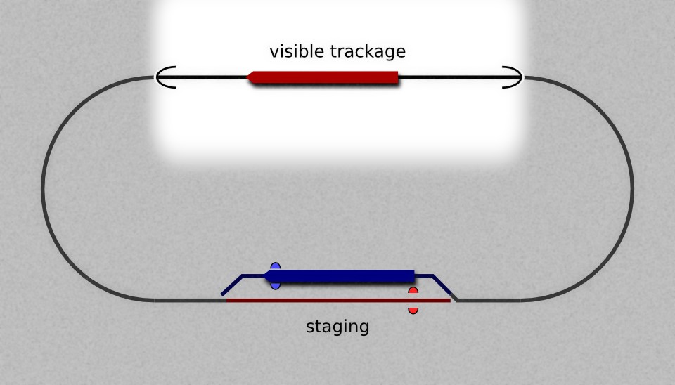
Chuck has an automated loop on his layout with two trains that take alternate laps in opposite directions. The new loop will work the same way.
Chuck commissioned an electronic circuit to automate this loop. Train A makes a trip around the loop, enters the siding, trips an infared detector, and stops. Track polarity reverses, and Train B makes its trip in the opposite direction before stopping at its own IR detector. Each staging track has a diode in its feeder, so its train stays parked when the current has the wrong polarity. At Chuck’s request, I provided the schematic for the simple one-transistor DC throttle I had built into the Gopher Valley Central. This circuit was combined with a microprocessor and two relays to yield the automatic reversing throttle. It was a big hit at shows; kids would watch the tunnel the train had just gone into, only to see a completely different train come out.
Enter the Arduino
Chuck built his new modules with an eye toward repeating the success of the automated loop, only this time, on one of the main lines. The Green Line (also known to Ntrakers as “the mountain division”) includes a long passing siding concealed in a tunnel, along with the spring switches, IR sensors, and diodes to match the original loop. Chuck’s layout has end-loop modules at either end, where the Green Line curves down and becomes the Red Line (also known as the front main). Chuck approached the guy who had built the first throttle for him, and asked him to build another, but no luck. Something about lost source code, or whatever; he simply didn’t want to do it. Having just demonstrated for him the throttle I had built into Lynn’s Z scale railroad, I was the next person he turned to.

One of Chuck’s new modules, showing the soon-to-be-hidden siding on the Green line. An infared detector can be seen on the left. The rotary switch has diodes to reduce voltage to the siding. A tunnel portal will be installed adjacent to the black blocks to the right.
“Can you build me a throttle like this one?” asked Chuck. He gave me copies of a hand-drawn schematic. I reviewed them.
“We can do better, Chuck,” I replied. I made a long list of proposed features that could be added to a new throttle. Chuck declined most of them for simplicity’s sake, but he liked the idea of having separate speed knobs for each direction. A set of specifications was agreed upon, and work commenced.
Naturally, the project was based upon Arduino. For those of you who don’t know, Arduino is a microprocessor prototyping platform. You take the board, attach components (LEDs, switches, sensors, motors, or whatever) to it, load it with some code, and let it do things for you. It’s “open source”—everything is fully documented. It’s been used worldwide for a wide variety of things, including model railroad applications.
Take a moment to Google “arduino model railroad.” I’ll wait right here.
So far, I’ve used Arduino for signals, throttles, and an improvised speedometer. What Chuck wanted wasn’t too far off from what I’ve already done. His old throttle controls track power with a pair of relays, one controlling polarity, one cutting current off when desired. An H-bridge chip, which can control speed and polarity to a DC motor, seemed like an obvious improvement. There are two such chips, the L293 and the L298, suitable for model-railroad applications. The L293 comes in a hobbyist-friendly DIP package, and is rated at 0.6 amps, plenty for a single N scale locomotive. I successfully used an L293 in Lynn’s throttle. The four-unit lashups that Chuck likes to run would likely push the limits of this chip, so I looked to the heftier L298, with a 1.5-amp rating. The through-hole version of this chip can’t just be dropped onto perfboard, and it needs external diodes, so it’s a little trickier to use. Luckily, there’s a ready-made L298 motor controller board ( a “shield,” in Arduino parlance) to suit this job.
For the controls that Chuck asked for, I made a separate front-panel circuit board with three potentiometers. The pots themselves don’t directly control the H-bridge; they just send analog signals back to Arduino’s microprocessor. How Arduino responds to inputs is entirely up to the code it’s running. If the code determines that the train should run, Arduino sends an appropriate signal to the H-bridge, and current goes to the rails. The front-panel board also has 5 LEDS: two to indicate direction, two to show train-detection status, and a central pilot light. These are also controlled via the code.

Front-panel board, with LEDs and potentiometers installed. Mockup of front-panel design and knobs are “ghosted” on.
So far, we have the Arduino board itself, the motor-controller shield, and a front-panel board. One more board, which stacks on top of the motor-controller shield, serves as a connection point for the front panel’s ribbon cable, and for the wires from the infrared detectors installed on the layout. Four circuit boards sounds like a lot for a throttle, but since two of them are off-the-shelf items, the whole throttle is simpler than it sounds.
The code, like all Arduino code, has an initialization routine, then enters an endless loop. On each pass of the loop, it reads sensors and knob settings, and processes that input according to which of four modes, STOP, START, RUN, or SLOW, is enabled. The H-bridge and the status LEDs are adjusted, and the mode itself advanced, accordingly. When entering the START mode, the direction is also changed, unless that direction has been disabled by turning its knob all the way down. If one direction is disabled, the train running in the other direction simply repeats laps.

L to R: Arduino Pro microcontroller, Sparkfun Ardumoto shield with L298 motor controller, protoboard with connectors for front-panel board and layout IR sensors.
In a microcontroller-based project, all the interesting stuff is happening with code. That’s one of the things I love about Arduino—I don’t have to be an EE to make a useful circuit. Need an LED? Add an appropriate resistor and plug it in. A knob? The potentiometer attaches with three wires. A motor chip? Just follow the data sheet. Connect all the individual widgets to the Arduino, and then write code that makes them play nice together. It’s kinda like the BASIC I pounded into those TRS-80s as a teenager, except that my code can now make real-world things happen.
With this kind of electronic freedom, it’s nice to be able to think through “user interface” issues. The guy who built Chuck’s first throttle put lots of knobs and switches on the panel. Chuck admitted to me that he never touches half of them. I try to take a minimalist approach, and put on the panel only what will actually get used. That’s another benefit of the Arduino approach—if I made a mistaken assumption in designing the circuit, it’s pretty easy to revise it. In some cases, there’s no need to change hardware at all; a modification to the code brings the circuit in line with expectations.
But enough blathering…
At this point, the hardware for Chuck’s new throttle is just about done. This week, I made some refinements to the code that have yet to be tested on Chuck’s layout. When we tried the throttle last weekend with the earlier code, it behaved as intended. Chuck had a four-unit set of Life-Like FAs pointed west, and two Kato AC4400CWs on the eastbound train. The Life-Likes are very slow runners compared to the Katos, but having two separate speed knobs took the fear out of running both trains hands-off from the same throttle. Instead of jerking into motion with the old throttle, the trains get up to speed gradually, thanks to the H-bridge. By changing a value in the code, I solved the problem of trains running too far past the infared detectors before stopping.
Chuck’s busy over the next few weeks, so I have an opportunity to build a front panel, polish the code a little more, and connect an appropriate power supply before final testing and installation.
And, oh yeah, George’s railroad, too. He’ll want that finished up before the holidays.
